3D Shapes
In this game, we will try to understand how the simplest 3D graphics work, using a cube as an example. Modeling these shapes can be divided into 3 parts:
the mathematical description of the shape
transformation: rotation and translation
projection onto a 2D screen plane and rendering
Let's look at each of these parts.
Cube Description
Assume that the cube is positioned exactly at the point
(0, 0, 0) and has an edge length of
2. Then each of its points can be described as follows:
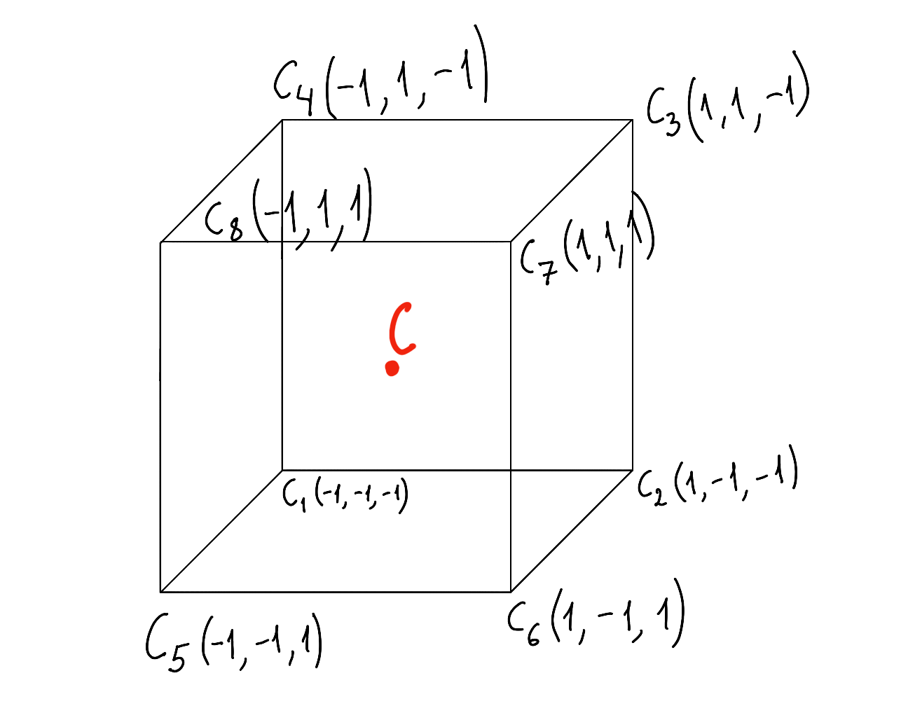
This gives us 8 vertices. The edges are the following segments:
(C1, C2)
(C2, C3)
(C3, C4)
(C4, C1)
(C5, C6)
(C6, C7)
(C7, C8)
(C8, C5)
(C1, C5)
(C2, C6)
(C3, C7)
(C4, C8)
If the cube edge has length
h, then to calculate the coordinates of vertex
i, each coordinate should be multiplied by
2h. For example, for vertex
1 with coordinates
C1(−1,−1,−1), the corresponding vertex of a cube with edge length
h will be
C1(−2h,−2h,−2h).
Transformation
First, let us consider cube rotation. A cube can rotate around each of its axes. Let us look at the case where the cube rotates around the
y axis. It looks like this:
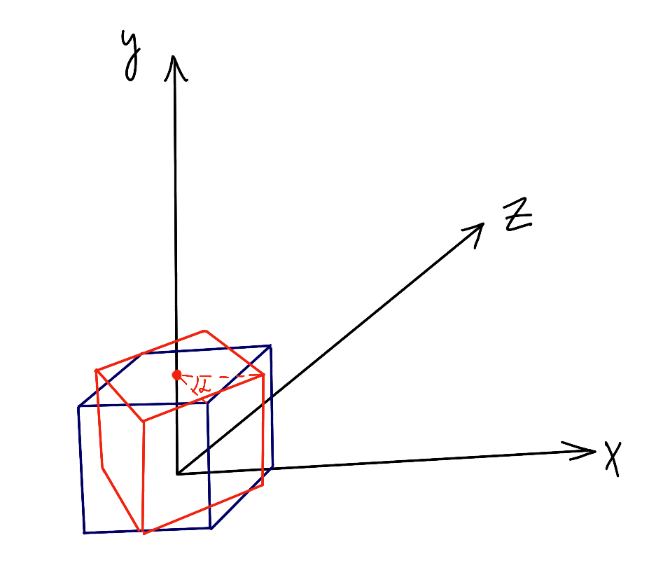
In this illustration, you can see that when rotating around the
y axis, the
y coordinate of each vertex does not change. So we can project the cube onto the
xz plane.
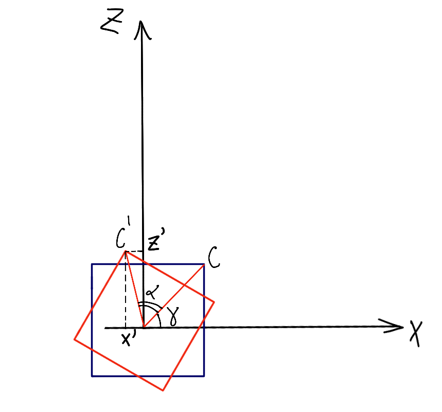
Here,
α is the angle of rotation relative to the vertex's initial position, and
γ is the initial angle of vertex
C relative to the
x axis.
C′(x′,z′) is the new position of the vertex after rotation.
Let
O be the center of the square and also the origin. Then it is clear that
OC=OC′=r. Hence:
Using trigonometric formulas, we can rewrite
x′ and
z′ a little:
Expanding the parentheses:
x′=r⋅cos(γ)⋅cos(α)−r⋅sin(γ)⋅sin(α)
z′=r⋅sin(γ)⋅cos(α)+r⋅sin(α)⋅cos(γ)
Knowing the formulas for the original coordinates, we substitute:
x′=x⋅cos(α)−z⋅sin(α)
z′=x⋅sin(α)+z⋅cos(α)
Then, by changing the angle
α, for example with mouse movement, we can calculate the coordinates of every point of the square using this formula.
In the same way, we can calculate rotation around the
x axis:
Here,
α is already the angle of rotation around the
x axis.
Rotation around the
z axis can be calculated in exactly the same way, but since on the screen the mouse can only move in two directions, we will not need it. You can do this calculation as homework 😊.
Next, to implement translation, it is enough to simply add the shift along each axis to each coordinate obtained after rotation. We will not go into detail here.
Projection Onto a Plane
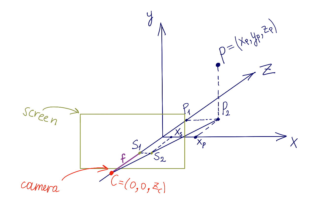
To display a 3D cube on a 2D screen, we need to define 2 things: the position of the screen or projection plane in space, and the position of the camera, which is the point from which we look at the screen. Suppose we have a point
P(xp,yp,zp) defined in space. We need to find the point
(xs,ys) defined in screen coordinates. Let us look at the image below:
Here,
S2(xs,0) is the projection of point
P onto the screen's
x axis. Consider the 2 triangles
(CS1S2) and
(CP1P2); they are similar. From triangle similarity:
P1(0,0,zp) is the projection of
P onto the
z axis, and
(xp,0,0) is the projection of
P onto the
x axis. Point
C (the camera) has coordinates
(0,0,zc). Therefore,
(CP1)=zp−zc. The focal length of the camera is
(CS1)=f. So the ratio above can be written as:
xpxs=zp−zcf
Hence:
xs=zp−zcf⋅xp
Similarly, we obtain:
ys=zp−zcf⋅yp
The values of
zc (the camera position) and
f (the camera focal length) are chosen manually.
Summary
Now you know how to move and rotate a cube in space, how to project it, and how to render it. The next step is implementation. Take this challenge on yourself 💪. Good luck!